Point Cloud to Mesh Conversion: The Complete 2026 Guide
Millions of raw scan points mean nothing until they become a usable 3D model. Here's exactly how point cloud to mesh conversion works — the workflow, file formats, software, accuracy, and what it costs.
What Is Point Cloud to Mesh Conversion?
What is point cloud to mesh conversion?
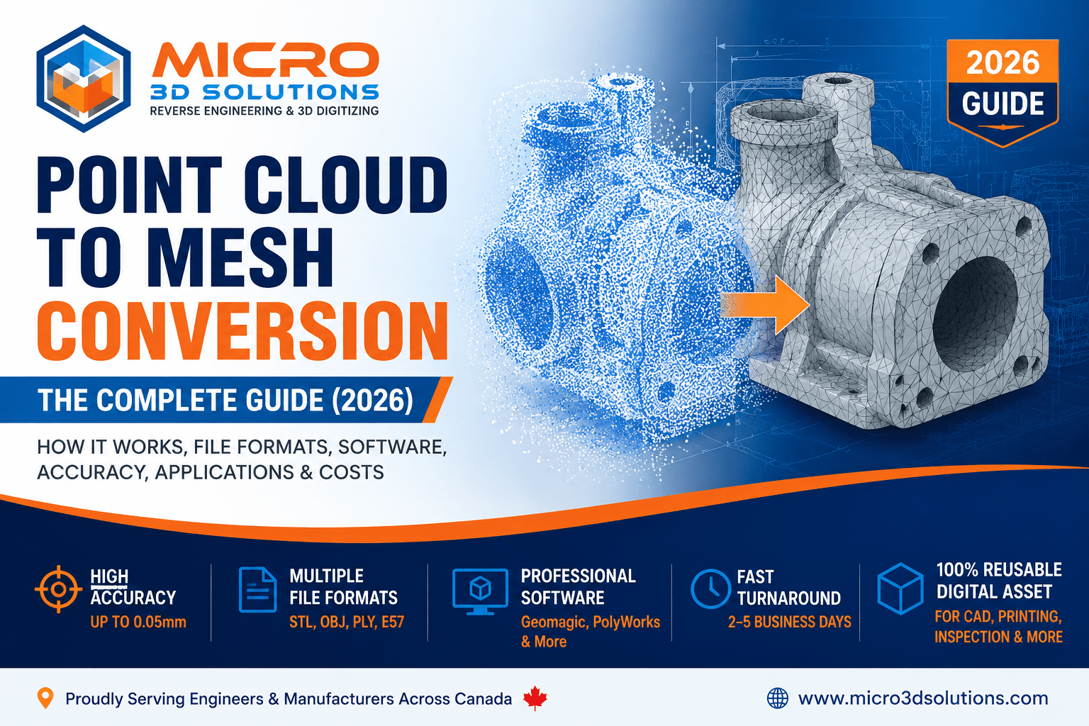
Point cloud to mesh conversion is the process of transforming a dense set of 3D scan points — a point cloud — into a continuous surface made of connected polygons, called a mesh. The mesh turns millions of disconnected points into a watertight, usable 3D model ready for inspection, reverse engineering, 3D printing, or CAD modeling.
When you 3D scan a physical object or environment, the scanner doesn't capture a solid model. It captures a point cloud — potentially tens of millions of individual XYZ coordinates floating in 3D space, each representing a single point on the object's surface. On its own, a point cloud is just data. You can view it and measure it, but you cannot 3D print it, run a proper inspection on it, or open it cleanly in most CAD software.
That's where conversion comes in. By connecting those points into a network of triangles (or other polygons), you create a continuous, watertight surface that software — and machines — can actually use. This single step is the bridge between the raw output of a 3D laser scanner and a practical engineering deliverable.
Point Cloud vs Mesh: The Core Difference
Understanding the distinction is the foundation of everything that follows:
- Point Cloud — a collection of discrete points with no connections between them. Think of it as a 3D "dot drawing" of the object. Accurate, but hollow and unusable for manufacturing on its own.
- Mesh — those points joined into a surface of connected polygons (usually triangles). It defines actual faces, edges, and a closed volume — making it printable, measurable, and CAD-ready.
A helpful analogy: a point cloud is like the individual stars in the night sky. A mesh is what you get when you connect those stars into constellations — suddenly there's a recognizable, continuous shape you can work with. The points were always there; meshing gives them structure and meaning.
In short: A point cloud tells you where the surface is. A mesh tells you what the surface is — a usable, continuous skin you can print, inspect, or rebuild into CAD.
Why Convert a Point Cloud to a Mesh?
Conversion isn't an optional polish step — for most projects, it's the only way to make scan data useful. Here's what a clean mesh unlocks:
- 3D printing & rapid prototyping — printers require a watertight mesh (usually STL). A raw point cloud simply cannot be sliced or printed, which makes meshing the first step in any 3D printing or rapid prototyping workflow.
- Dimensional inspection — a mesh can be compared against an original CAD model to produce a full deviation analysis, the backbone of 3D quality inspection.
- Reverse engineering — the mesh is the essential intermediate step before rebuilding an editable CAD model from a physical part.
- Visualization & simulation — meshes can be rendered, animated, or used in finite element analysis (FEA) and CFD simulations.
- Documentation & archiving — a mesh is a compact, reusable digital twin of an asset, part, or building that can be stored and referenced for years.
Whether the source is a precision machined component or an entire heritage building captured by LiDAR, meshing is the universal step that turns "scan data" into "engineering data."
The Point Cloud to Mesh Workflow
Professional conversion follows a consistent, repeatable process. Skipping or rushing any stage is where most quality problems originate.
Scan
Capture point cloud
Register
Align scans
Clean
Remove noise
Mesh
Triangulate surface
Refine
Fill, smooth, export
Data Capture (Scanning)
The object or environment is scanned using laser, structured-light, blue-light, or LiDAR technology. The choice of scanner determines the point cloud's density and accuracy — and therefore the achievable mesh quality.
Registration / Alignment
Most objects require multiple scans from different angles. Registration stitches these overlapping point clouds into a single, unified cloud using common reference points or targets, ensuring everything aligns in one coordinate system.
Cleaning & Noise Removal
Raw scans contain stray points, reflections, background clutter, and outliers. These are filtered out so the meshing algorithm works only with valid surface data. This stage has a direct impact on final accuracy.
Meshing (Triangulation)
The cleaned point cloud is converted into a polygon mesh. Algorithms connect neighbouring points into triangles, generating a continuous surface. Density settings control the balance between detail and file size.
Refinement & Repair
The mesh is inspected for holes, gaps, overlapping faces, and non-manifold edges. Holes are filled, the surface is smoothed where appropriate, and the topology is optimized to produce a clean, watertight model.
Export & Delivery
The finished mesh is exported in the required format (STL, OBJ, PLY) for its end use — 3D printing, inspection, or as the starting point for reverse engineering into CAD.
Point Cloud & Mesh File Formats Explained
Knowing which format to request — and why — saves time and avoids data loss. Point clouds and meshes use entirely different file types.
| Format | Type | Best For | Notes |
|---|---|---|---|
| .E57 | Point Cloud | Laser/LiDAR data exchange | Open standard; stores points + colour + metadata |
| .PTS / .PTX | Point Cloud | Leica & terrestrial scans | Common raw scanner output |
| .LAS / .LAZ | Point Cloud | LiDAR / surveying | Industry standard for aerial & GIS data |
| .STL | Mesh | 3D printing & inspection MOST COMMON | Geometry only — no colour or texture |
| .OBJ | Mesh | Visualization & rendering | Retains colour, texture & UV mapping |
| .PLY | Mesh | Scan data with colour | Stores per-vertex colour; great for full-colour scans |
| .3MF | Mesh | Modern 3D printing | Retains colour, materials & units that STL drops |
STL remains the workhorse for engineering and 3D printing because nearly every machine and inspection package reads it. If colour and texture matter — for example, archiving a heritage artifact — OBJ or PLY is the better choice.
Two of these formats are backed by formal standards, which is why they're preferred for long-term archiving and multi-vendor exchange: the .E57 format is defined by ASTM E2807, maintained by the ASTM E57 Committee on 3D Imaging Systems, while .LAS is the open LiDAR standard maintained by the American Society for Photogrammetry and Remote Sensing (ASPRS). When the output feeds a downstream 2D-to-3D or CAD conversion, choosing a standards-based format up front prevents data loss between platforms.
Software Used for Point Cloud to Mesh Conversion
The tool matters as much as the technique. Professional, engineering-grade conversion typically relies on:
- Geomagic Design X / Wrap — the industry benchmark for scan-to-mesh and scan-to-CAD with clean topology control.
- PolyWorks — favoured for inspection-grade meshing and dimensional analysis.
- Autodesk ReCap — strong for large LiDAR/architectural point clouds.
- Artec Studio — paired with structured-light and blue-light scanners.
- CloudCompare & MeshLab — capable open-source options for cleaning and basic meshing.
While free tools can produce a mesh, professional software is what delivers the watertight, accurate, manufacturing-ready result that downstream CAD and inspection work depends on. The difference shows up immediately when the mesh has to hold tolerance.
Point Cloud to Mesh vs Point Cloud to CAD
This is the single most common point of confusion — and choosing the wrong one wastes time and budget. They are not the same deliverable.
| Aspect | Point Cloud to Mesh | Point Cloud to CAD |
|---|---|---|
| Output | Polygon surface (STL/OBJ) | Editable parametric CAD model (STEP/SolidWorks) |
| Captures | Exact as-is geometry | Design intent & features |
| Editable? | Limited (sculpting only) | Fully editable features & dimensions |
| Best for | Inspection, 3D printing, visualization | Re-manufacturing, redesign, engineering |
| Effort | Faster & lower cost | More involved & higher value |
The simple rule: if you need to replicate or analyze an object exactly as it is, you need a mesh. If you need to modify or manufacture it, you need a CAD model — and the mesh is the stepping stone to get there. Many projects flow naturally from point cloud → mesh → parametric CAD model.
Accuracy, Resolution & Common Challenges
Mesh quality is governed by two things: the quality of the original scan, and the skill applied during processing. Professional conversions typically hold deviations within 0.05–0.1 mm of the source data for engineering parts — though the true accuracy of any optical 3D scanner should be assessed against recognized metrology standards rather than marketing figures. The accuracy of optical scanning systems is formally evaluated under VDI/VDE 2634 (acceptance and re-verification of optical 3D measuring systems), with quality parameters defined in line with ISO 10360 for coordinate measurement. Reputable providers state which scanner and standard their accuracy claims are based on.
What affects mesh accuracy?
- Scanner type — blue-light and structured-light deliver the finest detail for parts; LiDAR suits large objects and environments.
- Point cloud density — more points mean more detail, but also larger files and longer processing.
- Surface finish — shiny, transparent, or dark surfaces are harder to scan cleanly and may need preparation.
- Mesh resolution settings — too coarse loses detail; too fine creates unwieldy files with no real benefit.
Common challenges
Holes from occluded areas, noise on reflective surfaces, and overly heavy files are the three issues that surface most often. Experienced processing teams manage these by planning scan coverage carefully, filtering noise intelligently, and decimating the mesh to the right density for its purpose — keeping detail where it matters and reducing it where it doesn't.
Need a Clean, Accurate Mesh From Your Scan Data?
From a single precision part to an entire facility, our team turns raw point clouds into watertight, inspection-ready meshes — and into full CAD models when you need them.
Request a Free Quote →🇨🇦 Ontario-based team · Scan to Mesh & Scan to CAD · Fast turnaround
Applications Across Canadian Industries
Point cloud to mesh conversion quietly powers projects across nearly every sector Micro 3D Solutions serves:
Manufacturing & Tool and Die
Worn tooling and legacy parts are scanned and meshed for inspection or reverse engineering when no drawings exist.
Aerospace
Complex components are meshed for deviation analysis against CAD, verifying parts hold tight tolerances.
AEC & Heritage
LiDAR scans of buildings become meshes for as-built models, renovation planning, and heritage preservation.
Marine & Oil & Gas
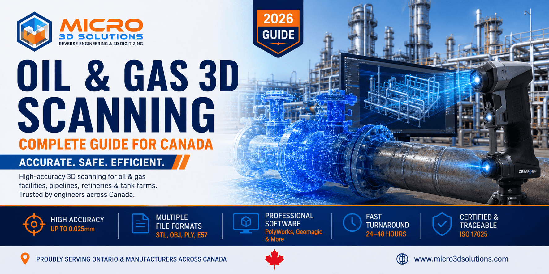
Hulls, valves, and pipework — including underwater scans — are meshed for inspection and replacement-part design.
Medical Devices
Anatomical and device scans are meshed for custom-fit prosthetics, orthotics, and surgical models.
3D Printing
Any object can be scanned, meshed, and 3D printed — the most direct route from physical to physical.
Cost & Turnaround in Canada
Pricing depends on object size, geometric complexity, and the accuracy required. As a general guide for the Canadian market:
- Simple parts — clean meshes can start around $150–$400 CAD.
- Complex assemblies or large environments — higher, scaling with point count and detail.
- Turnaround — most professional conversions are delivered within 2–5 business days; rush options are often available.
The most cost-effective projects start with a clear definition of the end use. A mesh destined for visualization doesn't need the same density as one bound for tight-tolerance inspection — and matching resolution to purpose keeps both cost and turnaround down.
Common Mistakes to Avoid
Requesting a mesh when you actually need CAD
If the part must be modified or manufactured, a mesh alone won't do. Define the end goal first to avoid paying for the wrong deliverable.
Over-dense meshes that nothing can open
A 200-million-polygon mesh isn't "better" — it's often unusable. Match density to purpose for files that are accurate and workable.
Skipping cleanup before meshing
Meshing noisy data bakes errors into the surface. Proper noise removal and registration up front is what makes the final mesh trustworthy.
Choosing the wrong export format
Exporting a full-colour heritage scan as STL discards the colour data. Match the format to whether you need geometry only or texture too.
Frequently Asked Questions
What is point cloud to mesh conversion?
It is the process of transforming a dense set of 3D scan points (a point cloud) into a continuous surface of connected polygons (a mesh) — turning raw, unusable scan data into a watertight 3D model ready for inspection, 3D printing, or CAD modeling.
What file formats are used for point clouds and meshes?
Point clouds are stored as .E57, .PTS, .PTX, .LAS, or .XYZ. Meshes are exported as .STL, .OBJ, .PLY, or .3MF. STL is the standard for 3D printing and inspection, while OBJ and PLY retain colour and texture.
What software converts point clouds to mesh?
Professional providers use Geomagic Design X/Wrap, PolyWorks, Autodesk ReCap, or Artec Studio. CloudCompare and MeshLab are capable open-source options for cleaning and basic meshing.
What's the difference between point cloud to mesh and point cloud to CAD?
A mesh is a polygon surface that replicates the object's exact geometry — ideal for inspection and 3D printing. A CAD model rebuilds the object with editable, parametric features and is required when the design must be modified or manufactured.
How accurate is point cloud to mesh conversion?
Professional conversions typically achieve deviations within 0.05–0.1 mm of the source data. Blue-light and structured-light scanning deliver the highest accuracy; LiDAR suits large objects and environments.
How much does point cloud to mesh conversion cost in Canada?
Costs vary with size, complexity, and accuracy. Simple parts may start around $150–$400 CAD, while complex assemblies or large environmental meshes run higher. Most conversions are delivered within 2–5 business days.
🔗 Related Reading
Reverse Engineering Services Explained
From physical part to editable CAD — the full 2026 workflow.
Guide3D Laser Scanning Explained (2026)
How scanning captures the point cloud that meshing relies on.
GuideLiDAR Scanner Explained (2026)
Capturing large objects and environments as point clouds.
GuideRapid Prototyping in Canada (2026)
Turn your finished mesh into a physical prototype, fast.
Final Thoughts
Point cloud to mesh conversion is the unglamorous but essential step that makes 3D scanning worthwhile. Without it, a scan is just a cloud of coordinates. With it, you have a watertight, reusable 3D model ready to be printed, inspected, archived, or rebuilt into CAD.
The quality of that mesh — and everything you do with it downstream — depends on doing each stage right: clean capture, careful registration, intelligent noise removal, and meshing at the correct resolution for the job. That's where experience separates a usable deliverable from a frustrating one.
Whether you're digitizing a single legacy part or an entire facility, getting the mesh right the first time saves time, budget, and rework. Talk to the Micro 3D Solutions team about turning your scan data into accurate, ready-to-use meshes.
About Micro 3D Solutions: We are an Ontario-based 3D digitizing and engineering services provider specializing in 3D laser scanning, point cloud to mesh, reverse engineering, CAD modeling, and 3D inspection for manufacturing, aerospace, AEC, marine, and energy clients across Canada. Learn more about our team and capabilities.
📚 Sources, Standards & References
- ASTM International — E2807: Standard Specification for 3D Imaging Data Exchange (E57 format). astm.org
- ASTM International — Committee E57 on 3D Imaging Systems. astm.org
- ASPRS — LAS Specification (LiDAR data exchange format). asprs.org
- VDI/VDE — VDI/VDE 2634: Optical 3D Measuring Systems — Acceptance & Re-verification. standards.globalspec.com
- ISO — ISO 10360: GPS — Acceptance and reverification tests for coordinate measuring systems. iso.org
- Software documentation — Autodesk ReCap, CloudCompare, MeshLab.
Published for Canadian readers in the 3D Digitizing & Reverse Engineering niche. Accuracy figures, cost ranges, and turnaround times reflect typical professional service-bureau parameters and vary by project, scanner, and applicable metrology standard. Updated for 2026.