2D to 3D Conversion Services for Canadian Manufacturers
Your legacy drawings hold real intellectual property — but CNC machines, FEA software, and 3D printers can't read them. Here's how engineer-led 2D to 3D conversion unlocks that value.
What Is 2D to 3D Conversion?
What is 2D to 3D conversion?
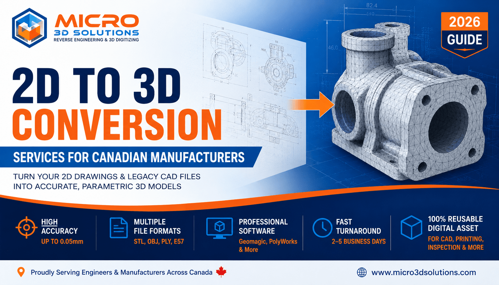
2D to 3D conversion turns a flat engineering drawing — a paper blueprint, PDF scan, or legacy DXF/DWG file — into a solid, parametric CAD model. It matters because CNC machines, FEA software, 3D printers, and PLM systems all need 3D geometry. A flat drawing won't work in any of them.
Canadian manufacturing archives hold millions of drawings like this: accurate on paper, but stuck in a format modern tools can't use. Converting that library to 3D unlocks re-manufacturing, simulation, rapid prototyping, and supplier collaboration — without redrawing anything from scratch.
Also called 2D CAD to 3D model conversion, the process takes a flat engineering drawing and rebuilds it as a three-dimensional parametric model. A 2D drawing captures views, cross-sections, tolerances, GD&T callouts, and material notes — but it stays flat on the page. A 3D parametric model adds depth: the geometry becomes solid, editable, and ready for CAD/CAM/CAE tools, CNC programs, 3D printers, and PLM systems.
This guide covers how our 2D to 3D conversion service works, which file formats we support, and how to get started with your own legacy drawings.
💡 Key Distinction: A 2D drawing describes a part. A 3D model IS the part, digitally — and that unlocks simulation, machining, inspection, and printing.
Why Convert 2D Drawings to 3D Models?
Canadian manufacturers in automotive, aerospace, heavy equipment, oil & gas, and tool and die sit on decades of drawings that represent real intellectual property. Converting that library to 3D unlocks value across the business:
- Re-manufacture legacy parts — build replacement components straight from the model, even without a surviving physical part.
- Drive CNC machining directly — the model feeds CAM software via STEP, something a 2D drawing can't do on its own.
- Run FEA and CFD simulation — test a design digitally before committing to manufacturing.
- Enable 3D printing — convert cleanly into printable STL or STEP files for 3D printing and rapid prototyping.
- Iterate faster — change one parameter instead of redrawing the part by hand.
- Inspect against CAD — quality inspection compares manufactured parts to the model with full deviation analysis.
- Integrate with PDM/PLM — the model plugs into systems like SolidWorks PDM and Teamcenter, feeding proper product data management.
- Collaborate with suppliers — share STEP or IGES files with partners who can't read your legacy formats.
A 3D model also removes the ambiguity of interpreting several 2D views at once — which is precisely where re-manufacturing errors and engineering-change delays originate.
🔧 In Practice: A manufacturer has only a faded paper blueprint for a discontinued machine component. Once it's rebuilt as a parametric 3D model, the part can go straight to a CNC machine — no re-drafting, no guesswork about the original design.
Our 2D to 3D Conversion Workflow
Automated tools that simply extrude 2D outlines produce incorrect geometry on anything but the simplest parts. Every conversion we do is done by hand, engineer to engineer. Here's how it works:
Intake
Review drawing
Rebuild
Geometry
Parametric
Driven by values
GD&T
MBD applied
QC
2nd engineer
Drawing Intake & Review
Send us your drawings in any format: paper originals, PDF scans, DXF, DWG, or legacy CAD files from systems like AutoCAD R14, ProE 2000, or older CATIA versions. Our engineers review every view, cross-section, GD&T callout, tolerance, and material spec before modelling starts.
Geometry Reconstruction
We rebuild the part from scratch in your target platform — SolidWorks, Siemens NX, AutoCAD 3D, CATIA, or Fusion 360. Every view and cross-section gets interpreted, including features that are ambiguous in 2D: hidden fillets, intersecting bores, chamfers only visible in section view. We handle everything from simple prismatic parts to complex freeform, multi-body assemblies.
Parametric Modelling
Every model we deliver is the product of true parametric 3D modelling: each dimension is driven by a named parameter or sketch relation, not hardcoded geometry. Change a shaft diameter or bolt pattern by editing one value, and the model updates automatically. That's the difference between a parametric model and a dumb solid.
GD&T & Tolerance Application
Where the original drawing carries GD&T per ASME Y14.5-2018 or ISO 1101, we apply model-based definition (MBD) annotations directly onto the 3D model — datums, feature control frames, and tolerance values built into the geometry itself. That creates one source of truth, instead of a model and drawing that can drift out of sync.
Manufacturing-Ready Output
We export the finished model in whatever formats you need: native CAD (SLDPRT, NX, CATIA), neutral exchange formats (STEP AP214, IGES, Parasolid), and manufacturing derivatives (STL, DXF flat patterns, CAM-ready STEP). Updated 2D drawings can be generated from the model too.
Quality Check & Delivery
A second engineer checks every model against the original drawing before delivery — dimensions, features, fits, and material specs. You get the files plus a short checklist of what was verified, and one revision cycle based on your feedback.
File Formats We Support
2D Input Formats
We accept 2D drawings in virtually any format — including obsolete ones most CAD shops can no longer open.
| Format | Source | Notes |
|---|---|---|
| Paper Blueprints | Physical originals | Scanned in-house, or courier to our GTA facility |
| Engineering drawings | Searchable or scanned — we handle both | |
| .DWG / .DXF | AutoCAD (any version) | Including legacy AutoCAD R12 onward MOST COMMON |
| .DGN | Microstation | Common in AEC and heavy civil drawings |
| TIFF / JPEG | Scanned blueprints | High-resolution scans, 300 DPI minimum |
| .DRW | Legacy ProE / Creo | Early 2D drawing files |
| .SLDDRW | SolidWorks 2D | Flat drawings never built out as 3D |
| .CATDrawing | CATIA V5 | Legacy drafting files |
3D Output Formats
We deliver the finished model in whatever 3D format best fits your workflow.
| Format | Type | Best For |
|---|---|---|
| .SLDPRT / .SLDASM | Native SolidWorks | Parametric editing, PDM integration, simulation |
| .PRT | Native Siemens NX | Aerospace & automotive OEM environments |
| .CATPart | Native CATIA V5 | Aerospace & automotive CATIA workflows |
| .STEP / .STP | Neutral (AP214/AP242) | Universal exchange — CAM, inspection, suppliers MOST VERSATILE |
| .IGS / .IGES | Neutral (legacy) | Older systems that can't read STEP |
| .X_T | Parasolid | Neutral solid exchange across most CAD platforms |
| .STL | Mesh | 3D printing & rapid prototyping |
| 3D .DXF | Cutting profiles | CNC plasma, laser & waterjet cutting programs |
STEP is defined by ISO 10303 — the international standard for exchanging product model data — which is why it remains the safest choice for long-term archiving and multi-vendor collaboration.
2D Drawing vs 3D Model: Why the Difference Matters
The practical gap between a flat drawing and a parametric 3D model shows up everywhere in production:
| Capability | 2D Drawing | 3D Parametric Model |
|---|---|---|
| CNC Machining | ✗ Not directly usable | ✓ Imports straight into CAM via STEP |
| FEA Stress Simulation | ✗ Not possible | ✓ Full mesh & boundary condition setup |
| 3D Printing | ✗ No printable geometry | ✓ Direct STL export |
| Design Modification | Manual redraw required | ✓ Change one parameter, model updates |
| Assembly Interference Check | Manual calculation | ✓ Automatic in CAD environment |
| Supplier Communication | Real interpretation risk | ✓ Unambiguous geometry |
| Quality Inspection | Limited to point checks | ✓ Full surface deviation analysis |
| PLM / PDM Integration | File storage only | ✓ BOM, revision & release management |
Industries We Serve
We deliver 2D to 3D conversion across the range of Canadian manufacturing and engineering sectors.
Tool & Die
Legacy punch, die, and mould drawings converted for CNC and EDM programming.
Automotive & Tier 1
Obsolete body, powertrain, and fixture drawings digitised to support re-manufacture.
Aerospace & Defence
Paper engineering orders converted into AS9100-traceable 3D models.
Heavy Equipment & Mining
Large frames, weldments, and structural assemblies modelled from hand-drafted blueprints.
Oil & Gas
Vessel, piping, flange, and valve drawings converted for plant layout and procurement.
Medical Devices
Legacy device drawings converted into ISO 13485-compatible 3D models.
Plastics & Injection Moulding
Parts and moulds modelled complete with draft angles, parting lines, and runners.
Marine & Naval
Hull sections, shaft arrangements, and structural assemblies converted to 3D.
🏭 Track Record: Our engineers have converted legacy drawings spanning 40+ years of Canadian manufacturing history — from hand-drafted blueprints to early AutoCAD R12 files and obsolete ProE/CADRA formats.
Need Accurate 2D to 3D CAD Conversion?
Whether you have a single drawing or hundreds of legacy blueprints, our engineering team can convert them into manufacturing-ready 3D CAD models.
Get a Free Consultation →🇨🇦 GTA, Ontario · SolidWorks · NX · CATIA · AutoCAD · 24–48h on simple parts
Common 2D Drawing Challenges We Solve
Incomplete or Damaged Drawings
Paper blueprints degrade over decades: folds, tears, faded lines, missing details. We cross-reference multiple views, apply industry-standard practice, and where needed, physically measure surviving parts to reconstruct complete, manufacturable geometry.
Multi-View Ambiguity
A 2D drawing uses top, front, and side views to describe a 3D object. Complex parts can read differently in each view — which is where automated software (and non-experts) misinterpret the shape. Our engineers resolve that ambiguity so the model matches the designer's original intent.
Legacy File Format Incompatibility
DWG files from 1990s AutoCAD R12/R14, DRW files from early ProE, VDA-FS surface data from old German machine tools — these all need specialised translators and manual repair. We have both the tools and the experience to open and reconstruct geometry from virtually any legacy format.
Assembly Drawings with Many Components
A single part is straightforward. An assembly drawing with 50+ components — each needing its own model, correctly mated and constrained — takes project management as much as CAD skill. We run a structured, BOM-driven workflow so nothing gets missed.
2D to 3D Conversion vs Reverse Engineering
How is 2D to 3D conversion different from reverse engineering?
2D to 3D conversion starts from a drawing — the dimensions are already known, and the task is rebuilding the geometry. Reverse engineering starts from a physical part — a 3D scanner captures the geometry, and the task is producing a CAD model from that scan data. Both end in a 3D model.
| Aspect | 2D to 3D Conversion | Reverse Engineering |
|---|---|---|
| Starting Point | An engineering drawing | A physical part |
| Dimensions From | Drawing callouts | 3D scan data measurement |
| Physical Part Needed? | No | Yes — required |
| Drawing Needed? | Yes — required | Optional, if helpful |
| Best For | Legacy drawing digitisation | Obsolete parts with no drawings |
| Combines With | 3D printing, CNC, simulation | Inspection & re-manufacturing |
We offer both, and often combine them. A client with a partial drawing and a worn part might need 2D to 3D conversion augmented by scan data to fill in the missing detail — we handle that hybrid work regularly. Learn more about our reverse engineering services, or read the full reverse engineering guide to see how scan-to-CAD workflows compare.
Why Choose Micro 3D Solutions
A few things set our conversion work apart from a typical CAD shop:
🇨🇦 GTA-Based Engineering Team
Work directly with Canadian engineers who understand local manufacturing needs — same time zone, same standards.
✋ Manual, Engineer-Led Conversion
No automated extrusion shortcuts. Every model is rebuilt by a qualified CAD engineer.
📐 Full Parametric Models
Editable from day one — never dumb solids imported from neutral formats.
💻 Delivered in Your Platform
SolidWorks, Siemens NX, CATIA, AutoCAD, Creo, or Fusion 360 — your choice.
📊 GD&T & MBD Ready
Applied per ASME Y14.5-2018, with model-based definition built into the geometry.
📂 Any Input Format Accepted
Paper, PDF, DWG, DXF, and obsolete legacy formats most shops can't open.
⚡ Fast Turnaround
Simple parts in 24–48 hours; complex assemblies scheduled to your project timeline.
✅ Second-Engineer QC
Every model verified against the original drawing before it reaches you.
Frequently Asked Questions
What file formats do you accept for 2D to 3D conversion?
Nearly every 2D format: paper blueprints (scanned or physical), PDF engineering drawings, DWG and DXF from any AutoCAD version, DGN from Microstation, SolidWorks drawing files (.SLDDRW), CATIA drafting files (.CATDrawing), and scanned TIFF or JPEG images. If your format isn't listed, contact us — we have translators for most legacy systems.
What 3D CAD platforms can you deliver models in?
Native models in SolidWorks, Siemens NX, AutoCAD 3D, CATIA V5, PTC Creo, and Fusion 360, plus neutral formats like STEP (AP214/AP242), IGES, Parasolid, and STL. Tell us your target format at the start of the project and we'll build to it.
Will the 3D model be parametric and editable?
Yes. Every dimension is defined by a sketch constraint or named parameter, so your team can modify the model by changing values, not rebuilding geometry. We don't deliver "dumb solids" imported from neutral formats — you get a native file that behaves like it was built from scratch.
Can you handle old paper blueprints and hand-drafted drawings?
Yes, regularly — hand-drafted blueprints from the 1950s through the 1990s, including pre-metric imperial drawings. Send high-resolution scans (300 DPI minimum) or courier originals to our GTA facility for scanning.
How accurate will the 3D model be compared to my original drawing?
Every dimension, tolerance, and GD&T callout is reproduced exactly, and a second engineer verifies critical dimensions before delivery. If the original drawing has errors or contradictions — common in older drawings — we flag them for your resolution rather than guessing.
Can you convert full assemblies, not just individual parts?
Yes — from simple two-part subassemblies to multi-hundred-component machines. We use a structured, BOM-driven workflow so every part is modelled individually and assembled with correct mates, with nothing missed even on assemblies with balloons and long parts lists.
How is 2D to 3D conversion different from reverse engineering?
Conversion starts from a drawing, with dimensions already known. Reverse engineering starts from a physical part, scanned in 3D and reconstructed from that data. Both end in a 3D model — we offer both, and often combine them when a client has partial drawings and a worn physical part.
What is the typical turnaround time?
Simple prismatic parts — shafts, flanges, brackets — usually ship within 24–48 hours. Complex freeform parts, heavy GD&T, or multi-part assemblies get scoped individually with a timeline estimate up front. Rush turnaround is available for urgent needs.
🔗 Related Reading
Reverse Engineering Services Explained
From physical part to editable CAD — the 2026 workflow.
Guide3D Modeling Services Explained
CAD, BIM and digital twin modelling for manufacturers.
GuidePoint Cloud to Mesh Conversion
Turning raw 3D scan data into usable models.
Guide3D Metrology Services in Canada
Verify your manufactured parts against the CAD model.
The Bottom Line
Legacy 2D drawings hold real value — but only once they're rebuilt as parametric 3D models. Converting them unlocks CNC machining, FEA simulation, 3D printing, faster design changes, and cleaner supplier collaboration, all without redrawing a single part by hand.
Our team handles that conversion end to end: intake, geometry reconstruction, parametric modelling, GD&T application, and a second-engineer quality check before delivery — in the CAD platform your team already uses.
If you have legacy drawings sitting idle, that's the next step. Talk to the Micro 3D Solutions engineering team about converting them.
About Micro 3D Solutions: We are a GTA, Ontario-based 3D digitizing and engineering services provider specializing in 2D to 3D conversion, 3D CAD modeling, reverse engineering, 3D laser scanning, and quality inspection for manufacturing, aerospace, medical, and heavy equipment clients across Canada. Learn more about our team.
📚 Official References & Standards
- ASME — Y14.5-2018: Dimensioning and Tolerancing (GD&T). asme.org
- ASME — Y14.41: Digital Product Definition Data Practices (Model-Based Definition). asme.org
- ISO — ISO 10303 (STEP AP214/AP242): Standard for the Exchange of Product Model Data. iso.org
- ISO — ISO 1101:2017: Geometrical Product Specifications (GPS) — Geometrical Tolerancing. iso.org
- National Research Council Canada — Measurement science and manufacturing standards. nrc.canada.ca
Published by the engineering team at Micro 3D Solutions, GTA, Ontario — specialists in 2D to 3D CAD conversion and manufacturing-ready 3D models. Turnaround times and capabilities vary by project scope and drawing condition. Updated for 2026.