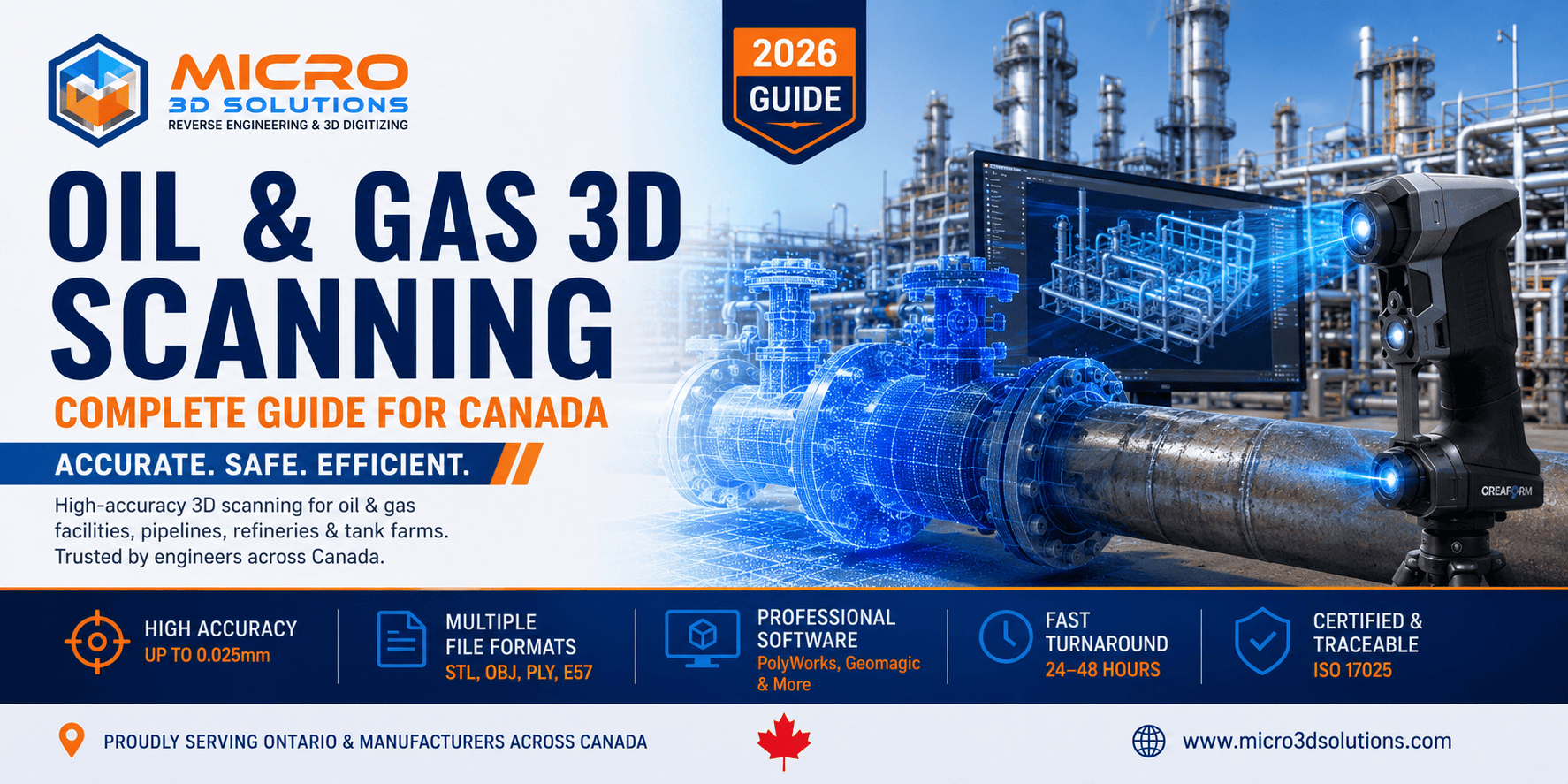
Oil & Gas 3D Scanning: Complete Guide for Canada
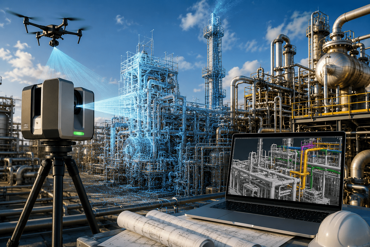
Oil & gas 3D scanning uses laser scanners or drones to capture millions of precise measurement points — a "point cloud" — of a pipeline, refinery, or tank farm, giving operators exact as-built dimensions without shutting down production.
Get a Free Quote →What's Inside This Guide
By the engineering team at Micro 3D Solutions, GTA, Ontario — specialists in 3D laser scanning and as-built documentation for Canadian industrial facilities.
📋 Table of Contents
- What Is Oil & Gas 3D Scanning?
- Why Oil & Gas Facilities Need 3D Scanning
- How Oil & Gas 3D Scanning Works
- Applications Across Upstream, Midstream & Downstream
- Scanning Technologies: Which One Fits Your Site
- Canadian Regulatory & Industry Standards
- Digital Twins & Ongoing Facility Management
- Common Challenges We Solve
- Benefits of 3D Scanning for Oil & Gas Operators
- 3D Scanning vs. Traditional Field Surveying
- Why Choose Micro 3D Solutions
- Frequently Asked Questions
What Is Oil & Gas 3D Scanning?
What is oil & gas 3D scanning?
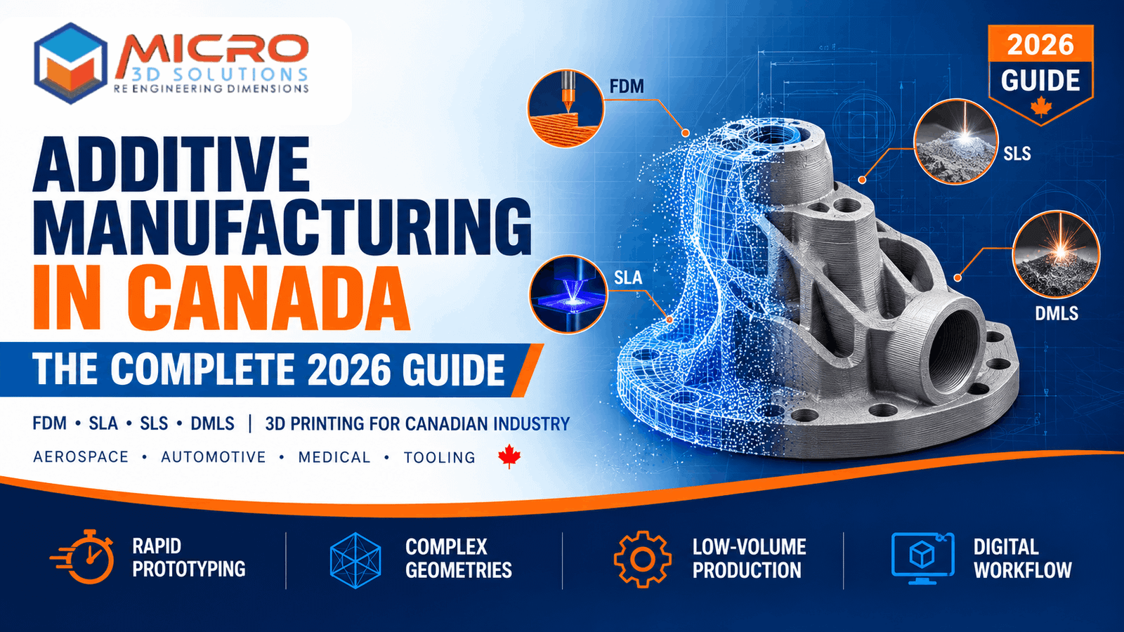
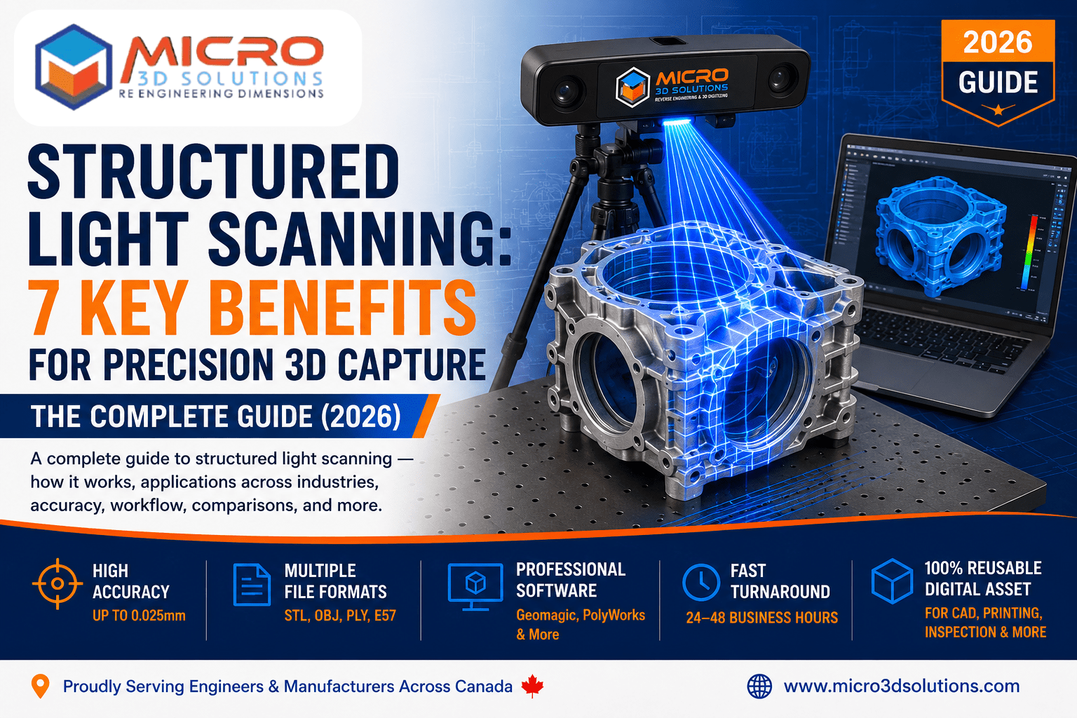
Oil & gas 3D scanning is the use of terrestrial laser scanners, mobile mapping systems, or drone-mounted LiDAR to capture the exact geometry of process equipment, piping, structures, and terrain at an oil & gas facility.
The scanner measures distance using laser pulses (time-of-flight or phase-shift), recording millions of X, Y, Z coordinates per second. The result is a point cloud: a dense, geometrically accurate digital copy of the facility, with accuracy that depends on equipment and site conditions — this kind of industrial asset digitisation is what makes the rest of the workflow possible.
Why Oil & Gas Facilities Need 3D Scanning
Most Canadian oil & gas assets were built before 3D CAD existed. Piping isometrics, plot plans, and structural drawings were updated inconsistently over decades of tie-ins, retrofits, and repairs. By the time an engineering team plans a new project, the drawings on file often don't match the plant.
Manual field verification — sending surveyors or engineers to measure pipe runs and clearances by hand — is slow, and it means putting people in hazardous, high-pressure, or confined areas. 3D scanning solves both problems at once.
Outdated or Missing As-Built Drawings
A scan captures the facility exactly as it exists today, in hours, not weeks — replacing drawings that no longer reflect what's actually built.
Costly Plant Shutdowns for Surveying
Most scanning is done live, without halting production, avoiding the cost of a shutdown just to gather field measurements.
Personnel Safety in Hazardous Zones
Scanners and drones reduce the time crews spend in confined or elevated areas, cutting down on unnecessary exposure to hazardous conditions.
Clash Detection on Retrofit Projects
New piping and equipment can be designed directly against real, scanned geometry, catching interferences before construction instead of in the field.
Turnaround and Shutdown Planning
Accurate models let planners sequence work before crews are on-site, tightening the schedule for a planned outage.
Regulatory and Insurance Documentation
Point clouds provide a defensible, timestamped record of as-built condition — useful for both regulatory files and insurance documentation.
How Oil & Gas 3D Scanning Works
A typical scanning project for a Canadian oil & gas facility follows a consistent process, whether the site is a single tank or an entire refinery unit.
Site Assessment & Scan Planning
Our team reviews the facility layout, identifies scan station locations, and plans around live operations, confined spaces, and any hot-work or permit requirements specific to the site.
Field Data Capture
Terrestrial laser scanners capture piping, vessels, and structural steel from multiple stations around the site. Drone-mounted LiDAR or photogrammetry covers tank farms, flare stacks, and areas difficult to reach from ground level.
Point Cloud Registration
Individual scans are aligned into one unified point cloud using survey control points or cloud-to-cloud registration software, producing a single accurate dataset of the entire facility.
3D Modelling
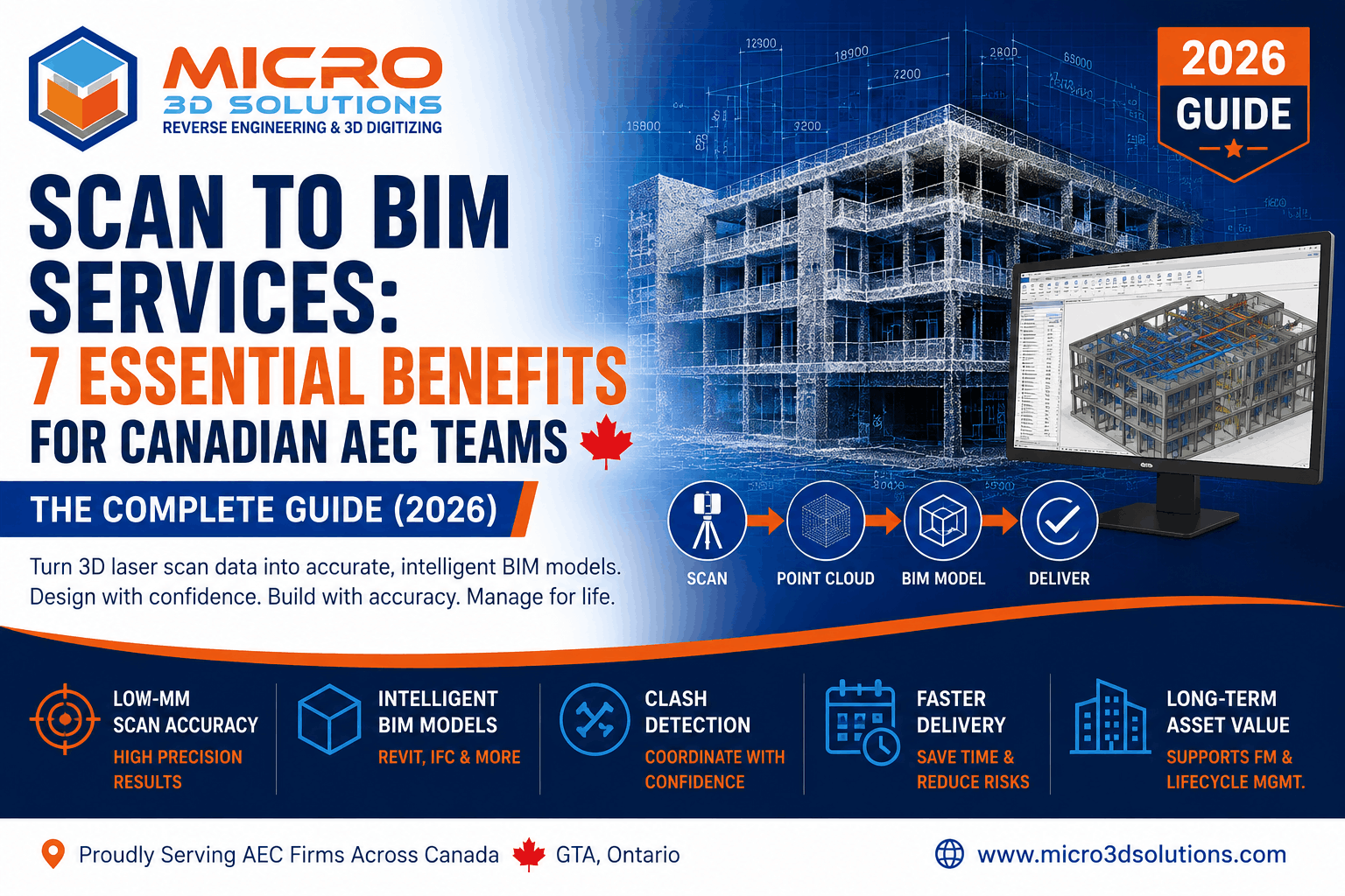
Engineers convert the point cloud into CAD as an intelligent 3D model — piping modelled to spec, vessels and structural steel as parametric objects — in platforms like AutoCAD Plant 3D, Navisworks, SolidWorks, or Revit.
Deliverables & Handover
You receive the registered point cloud, the 3D model, and derivative outputs: updated P&IDs, isometric drawings, plot plans, or clash detection reports, in the format your engineering team already works in.
Applications Across Upstream, Midstream & Downstream
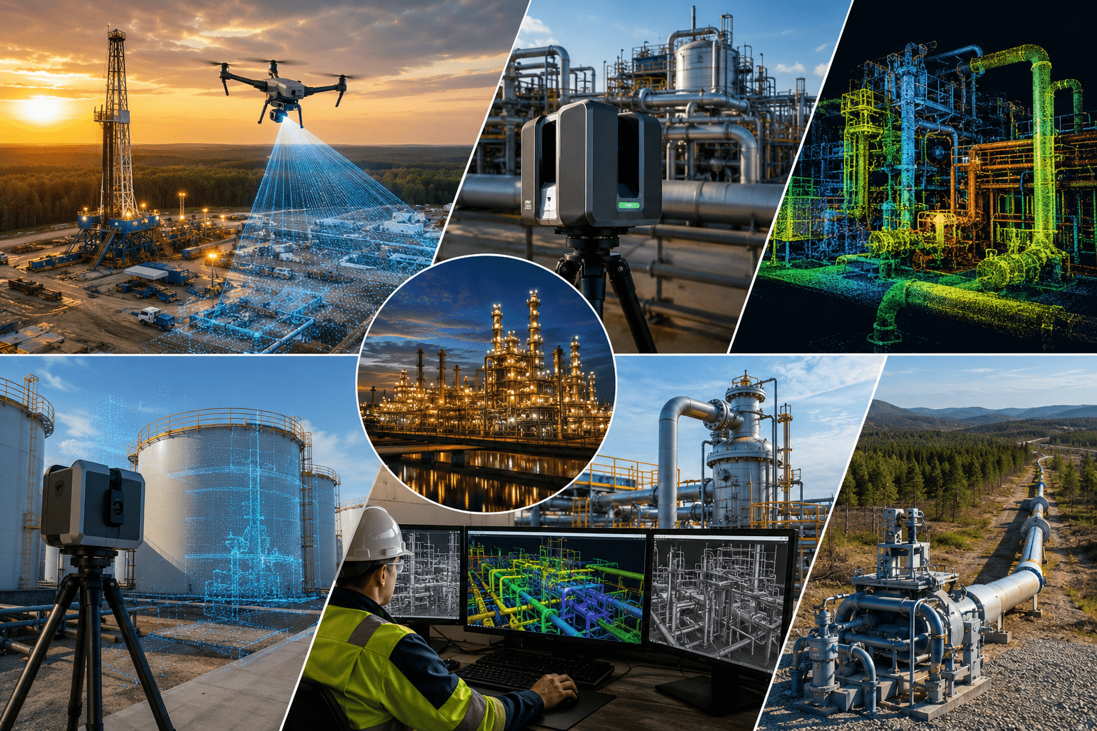
3D scanning applies across the full oil & gas value chain, from wellsites to refineries. The scope and scanning approach shift depending on where in the value chain the facility sits — a compact wellsite pad calls for a quick single-visit scan, while a refinery process unit with dense piping needs a more methodical, multi-day capture plan.
Upstream
Wellsite layout, gathering systems, and drilling rig clearance verification — capturing pad geometry and equipment spacing before new infrastructure goes in.
Midstream
Pipeline right-of-way mapping, compressor stations, pump stations, and tank farms — where accurate as-built data supports tie-ins and integrity planning along the line.
Downstream
Refinery process units, distillation columns, piperacks, and storage tanks — dense, congested areas where millimetre accuracy matters most for retrofit design.
Oil Sands
Extraction facilities, upgrader units, and tailings infrastructure — large, complex sites where scanning replaces years of incremental drawing updates.
Offshore
Platform topsides and module fabrication verification, relevant to offshore projects where fit-up accuracy before transport is critical.
LNG & Petrochemical
Cryogenic piping, storage spheres, and loading terminals — specialised geometry that benefits from a precise as-built reference for future modification work.
Scanning Technologies: Which One Fits Your Site
Terrestrial Laser Scanning (TLS)
Best for piping, vessels, structural steel, and process units. Terrestrial laser scanning projects typically achieve approximately 2–5mm accuracy, depending on equipment, site conditions, and workflow — making it the standard choice wherever millimetre precision matters.
Mobile Mapping (SLAM)
Best for long pipeline corridors and walkable plant areas where fast capture matters more than the highest precision. Accuracy typically falls in the 1–3cm range, depending on conditions and equipment.
Drone LiDAR
Best for tank farms, flare stacks, elevated structures, and large open sites that are difficult or unsafe to reach from the ground. Accuracy typically falls in the 2–5cm range, depending on flight conditions and sensor quality.
Photogrammetry
Best for visual documentation and texture-rich models on lower-budget projects. Accuracy varies more widely here, roughly 1–10cm depending on camera quality and image overlap — adequate when visual context matters more than exact dimensions.
Most facility-wide projects combine two or more of these: terrestrial scanning for process units where millimetre accuracy matters, and drone or mobile mapping for large open areas where speed matters more than precision.
Canadian Regulatory & Industry Standards
Oil & gas 3D scanning deliverables in Canada are typically produced to align with the standards your facility already operates under. Knowing which standards apply to your site helps determine scan accuracy requirements and what documentation format your inspection or regulatory team will expect from the final model.
CSA Z662
Canada's oil and gas pipeline systems standard. As-built documentation from a scan supports the compliance record-keeping this standard requires.
AER Directives (Alberta)
Alberta Energy Regulator requirements for facility documentation and integrity management — relevant to any Alberta upstream or oil sands site.
TSSA (Ontario)
The Technical Standards & Safety Authority governs pressure vessel and piping documentation for Ontario facilities, including refineries.
API 653 / API 570
Tank and piping inspection standards from the American Petroleum Institute. Point cloud data supports the wall-thickness and deformation checks these standards call for.
ISO 19901 Series
Offshore structures standards relevant to offshore platform projects, covering topsides and structural verification.
We don't certify compliance — that's your regulatory or inspection engineer's role — but an accurate as-built model gives that engineer a reliable record to work from, instead of an outdated drawing.
Digital Twins & Ongoing Facility Management
A point cloud captured once doesn't have to be a one-time deliverable. Many Canadian operators now treat scan-based digital twin creation as an ongoing part of facility management: a continuously referenced 3D record of the facility that engineering, maintenance, and operations teams all work from.
Instead of re-surveying for every project, teams pull directly from the existing model to plan a tie-in, check clearance for new equipment, or verify as-built condition after a repair. Re-scanning specific areas after a major turnaround keeps the twin current without redoing the whole facility.
Need Accurate 3D Scanning for Your Oil & Gas Facility?
Whether it's a single tank, a pump station, or a full refinery unit, our team can capture and model your facility for retrofit design, turnaround planning, or compliance documentation.
Request a Free Consultation →Common Challenges We Solve
Congested Piperacks & Process Units
Dense piping, cable trays, and structural steel create sightline problems for a single scanner position. We plan multiple overlapping scan stations so every pipe run and connection is captured, even in the most congested units.
Confined & Elevated Areas
Vessel interiors, pipe racks, and elevated platforms are difficult and sometimes hazardous to measure by hand. Drone LiDAR and compact scanners reach these areas with minimal personnel exposure, cutting down on confined-space entries and elevated work.
Sites With No Reliable As-Built Drawings
Many older facilities have drawings that reflect the original design, not the decades of field modifications since. Scanning captures the facility exactly as it stands today, so the new model becomes the accurate reference going forward, not another approximation.
Coordinating Around Live Operations
Scanning has to work around shift schedules, permits, and active work fronts. Our team plans capture sequencing with your site's operations group so scanning doesn't interfere with ongoing work.
Benefits of 3D Scanning for Oil & Gas Operators
- Millimetre-accurate as-built data, replacing drawings that no longer reflect the facility
- Faster turnaround planning — model the work before crews arrive on-site
- Reduced personnel exposure in confined spaces and elevated or hazardous areas
- Fewer field surprises and less rework on retrofit and tie-in projects
- A reusable digital record for future projects, not a one-time survey
- Clash detection between new design and existing piping, steel, and equipment
The return on a scanning project usually shows up on the first retrofit or turnaround it supports: fewer field fit-up issues, less standby crew time waiting on design clarifications, and a design package that matches the actual site from day one.
3D Scanning vs. Traditional Field Surveying
Data Captured
Traditional surveying records selected points only. 3D laser scanning captures millions of points — everything within view of the scanner, not just the dimensions someone thought to measure.
Field Time
Traditional surveying can take days to weeks depending on scope. Laser scanning typically covers most sites in hours to a few days.
Rework Risk
Traditional surveying carries higher rework risk — missed measurements are often only discovered back at the office. Laser scanning captures the full geometry once, so there's far less risk of a missing dimension.
Confined Space Exposure
Traditional surveying requires direct measurement, often inside confined or elevated areas. Laser scanning minimizes this — most capture happens from safe standoff points.
Deliverable
Traditional surveying produces 2D drawings and spot dimensions. Laser scanning delivers a full 3D model, with 2D drawings available on demand from the same dataset.
Reusability
Traditional survey data is limited to its original scope. A laser scan's point cloud supports future projects too, without a repeat site visit.
Why Choose Micro 3D Solutions
Our team brings a few things to Canadian oil & gas scanning projects that a general industrial scanning services provider typically doesn't:
- Engineers who model the point cloud into intelligent CAD — the same reverse engineering expertise we apply across industries, not just raw scan data
- Experience working around live operations, permits, and confined-space protocols
- Delivery in the platform your engineering team already uses — Plant 3D, Navisworks, SolidWorks, Revit
- Combined terrestrial, mobile, and drone capture for full-site coverage
- GTA-based team serving clients across Canada
What to Prepare Before a Scanning Project
A short intake call speeds up planning and quoting. It helps to have the following ready:
- Approximate site boundaries or the specific units/areas you want scanned
- Any existing drawings, even outdated ones — they help with scan planning, not accuracy
- Site access requirements: safety orientation, permits, escort needs
- Target deliverable format and the CAD platform your engineering team uses
- Project timeline, especially if scanning needs to align with a shutdown or turnaround window
Frequently Asked Questions
What is 3D scanning used for in the oil and gas industry?
3D scanning captures accurate as-built geometry of pipelines, refineries, tank farms, and process equipment. It's used for retrofit design, turnaround planning, clash detection, regulatory documentation, and digital twin creation, without relying on outdated drawings.
How accurate is 3D laser scanning for industrial facilities?
Terrestrial laser scanning typically achieves approximately 2–5mm accuracy, depending on equipment, site conditions, and workflow — suitable for piping and equipment design. Drone LiDAR and mobile mapping trade some accuracy (roughly 1–5cm) for faster coverage of large or hard-to-reach areas like tank farms and flare stacks.
Does 3D scanning require shutting down the facility?
No. Most scanning is performed during live operations, working around existing traffic and safety protocols. Full shutdowns are only needed if the scan area itself is inaccessible during operation, which is uncommon.
What deliverables do we receive from a 3D scanning project?
A registered point cloud, an intelligent 3D model (piping, structural steel, vessels), and any derivative outputs you need — updated P&IDs, isometrics, plot plans, or clash detection reports — in your preferred CAD platform.
How is 3D scanning different from traditional surveying?
Traditional surveying captures selected points and takes days to weeks. Laser scanning captures millions of points in one pass, covering the full geometry of a site in hours to a few days, with far less risk of a missed measurement requiring a return site visit.
Can 3D scanning support pipeline integrity and compliance documentation?
Yes. Point cloud data supports wall-thickness comparisons, deformation tracking, and as-built records referenced under standards like CSA Z662 and API 570. Final compliance sign-off remains with your regulatory or inspection engineer.
Can scan data be reused for future projects?
Yes — that's one of the biggest advantages over traditional surveying. A registered point cloud stays valid until the facility physically changes, so future retrofit, maintenance, or expansion projects can pull from the same dataset instead of commissioning a new survey.
How much does oil & gas 3D scanning cost?
Cost depends on site size, complexity, and the scanning method used — a single tank or wellsite is far less than a full refinery unit. Most projects are quoted after a short scope call covering site size, access, and deliverable format. Contact us for a project-specific estimate.
What areas of Canada do you serve for oil & gas scanning?
We serve clients across Canada, deploying to site as scanning projects require — from upstream and midstream facilities to refineries and offshore platforms.
The Bottom Line
Oil & gas facilities run on drawings that rarely match reality after years of retrofits and repairs. Brownfield plant scanning closes that gap with an accurate record of what's actually built, without shutting down operations or putting crews in unnecessary risk.
Whether you're planning a turnaround, a tie-in, or a full digital twin of a process unit, an accurate point cloud and 3D model is the starting point. Our team handles that capture and modelling end to end, delivered in the format your engineers already use. Talk to the Micro 3D Solutions team about your next scanning project.
📚 Official References & Standards
- CSA Group — CSA Z662: Oil and Gas Pipeline Systems. csagroup.org
- Alberta Energy Regulator (AER) — Directives on facility documentation and integrity management. aer.ca
- API — API 653: Tank Inspection, Repair, Alteration, and Reconstruction. api.org
- API — API 570: Piping Inspection Code. api.org
- ISO — ISO 19901: Petroleum and Natural Gas Industries — Specific Requirements for Offshore Structures. iso.org
- Technical Standards and Safety Authority (TSSA) — Ontario pressure vessel and piping standards. tssa.org